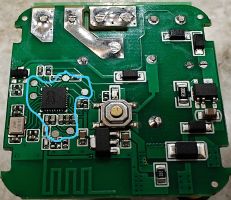
If you plan to make more than just a few switches, chances are you want to make this pogo pin jig. This jig is compatible with any single switch board that follows the pattern of 6 contact pads around the chip:
All single switches covered in this project share this layout, so to make it easy on yourself go ahead and make the jig! You will need:
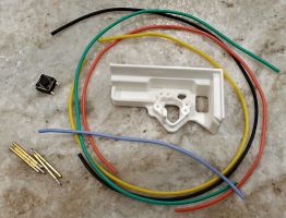
- 3D-printed jig body (step and fusion files are avaiable as well)
- A few lengths of wire (I prefer flexible wires with silicone insulation)
- Tactile switch (see buying guide for sources)
- Pogo pins (see buying guide for sources)
Print the jig body and test it. The pogo pin must fit in the hole, but it has to be a really tight squeeze. If it wobbles inside, it might end up tilted and will not align with a pad on the board. If it’s too tight or too loose, please adjust the Hole Expansion setting in your slicer and try again.
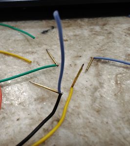
I suggest using wires of different colors to make the assembly process more error-proof. I used 5 pieces of wire about 6 inches long each. Black for ground, red for power, green and yellow for RX/TX lines, blue for button. First step is to strip about 1/16” of insulation from both ends of all the wires and solder one on the end of each pogo pin. Please don’t hold pins with your fingers, use tweezers or pliers - things become hot very quickly. Better yet hold it with a clip. Use some flux and tin the end of each pin first. Once it is tinned, put a fluxed wire on top, add some solder to the iron tip and join the two together. After soldering is done, please check that pins are still springy and move freely. If not, desolder the wire, throw the pin away and try another one.
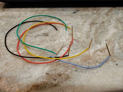
Then you need to cut the blue wire in half (or whichever color you are using for button connection). Strip both new ends and tin them. Solder the new wire to the black wire on the pogo pin (or whichever color you use for ground). It is a bit tricky to hold everything, so use the 3rd hand.
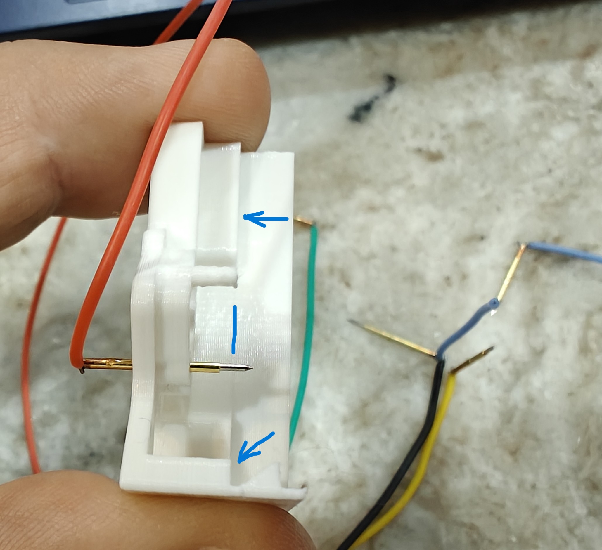
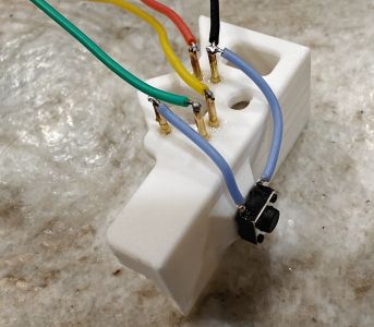
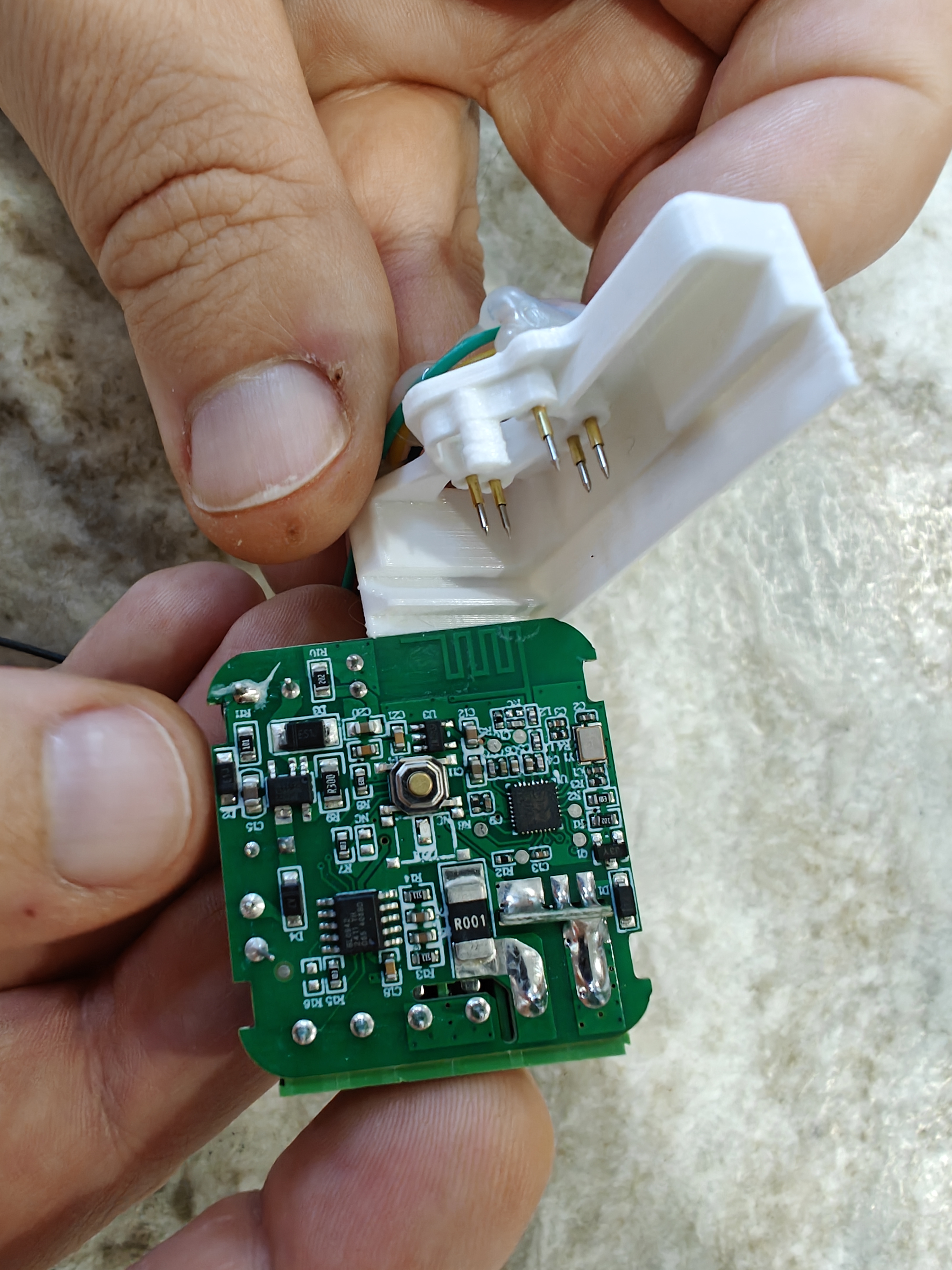
Press the pins into the jig body. It is very important to push them to the right depth. The moving part of the pin must protrude past the board stopping shelf. If it doesn’t protrude, then it will not make good contact. If it protrudes too far, then the board will not be able to get in position.
 (click to enlarge)
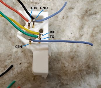
Pay attention to fit the pins in their proper places. Here’s how it should like after all the pins are pressed in. If you use different colors, just be sure to put 3.3, GND, RX, TX, CEN pins in their corresponding locations.
I like to add super glue around each pin at this stage. Once the glue solidifies (feel free to use the accelerator) the pins will not go anywhere. Before moving on, just double-check the springiness of every pin. Sometimes the glue seeps between the pin and the jig body. If any of the pins is seized, try to remove the glue with a knife and wiggle it to freedom. Otherwise start over.
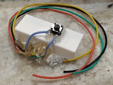
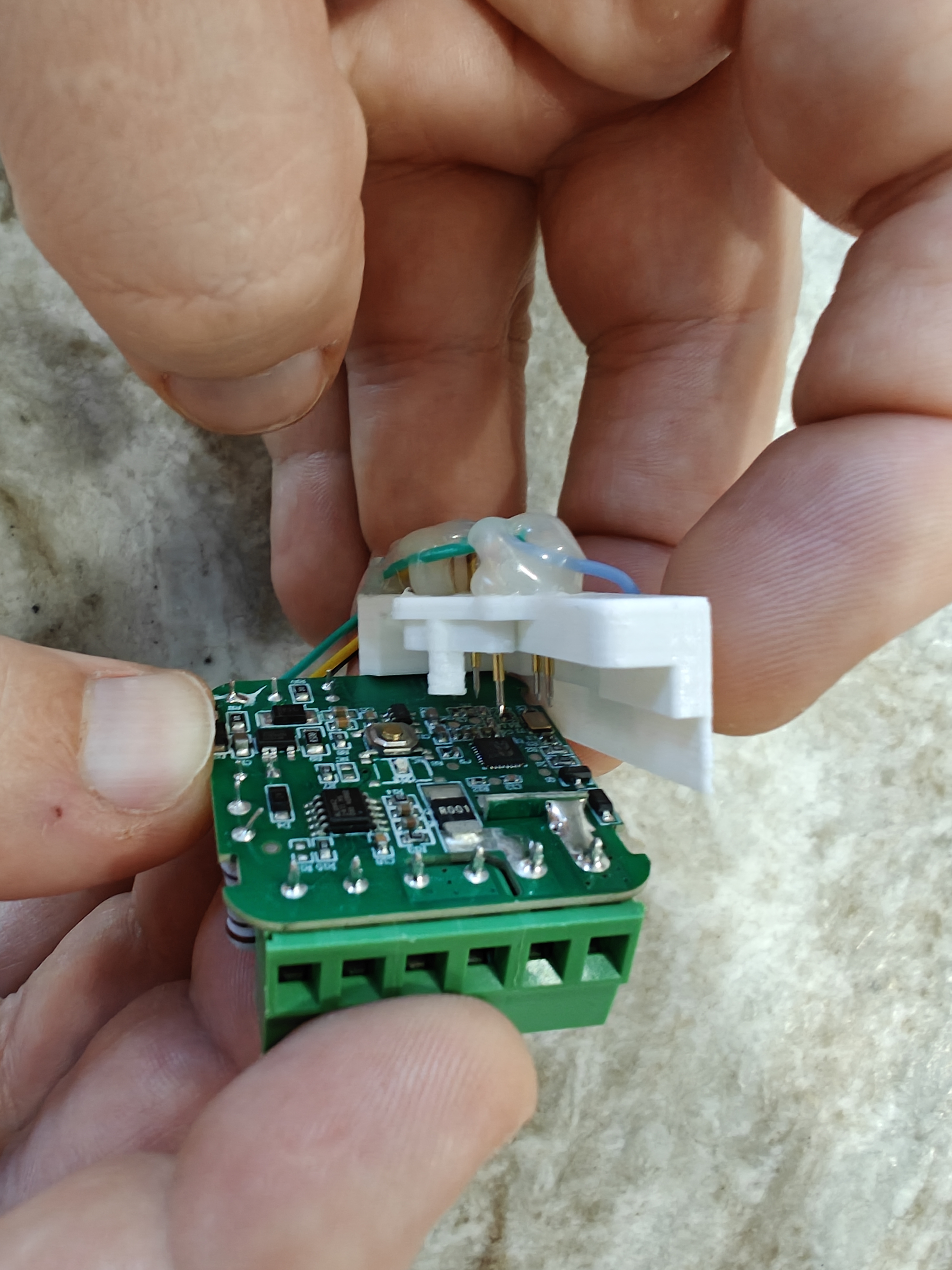
Let’s prepare the button next. Use pliers to straighten 2 leads on one side. This will simplify the soldering once it is glued in place.
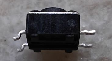
Next super-glue the button onto its pedestal on the side of the jig body. Make sure straight leads are facing the pins. Solder blue wires to the button leads.
After that I like to apply some hot glue on top of everything. This is done to prevent the pins from sliding out (i know, we super-glued them in, but better safe than sorry) and to provide some stress relief to the wires. What could be worse than destroying your freshly made jig by accidentally tugging on a wire?
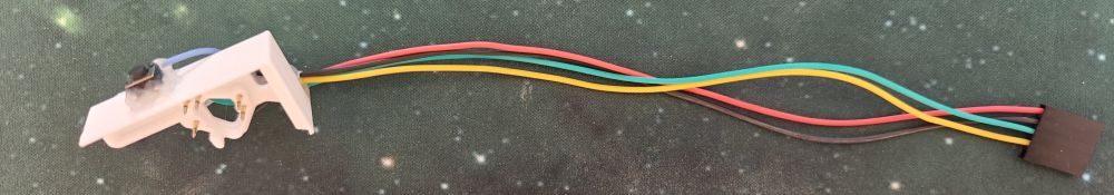
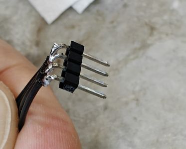
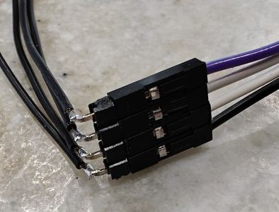
Now you are almost done. The only remaining part is to connect it to your USB-UART adapter. There are many ways to do it. My favorite is to crimp it with dupont crimps. This way I can put them into a single connector in an order that matches that of my UART board.
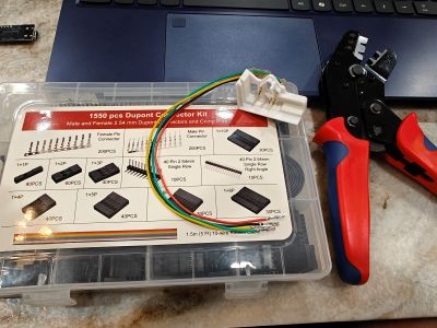
Another option is to finally use one ow those pin header pieces you desoldered from some board a long ago. You can then use the female-female cable that likely came with the adapter.
You can simply solder it to your UART board as a last resort.
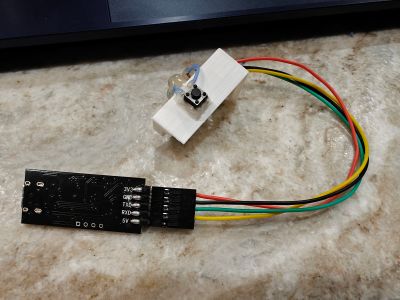
Using the jig
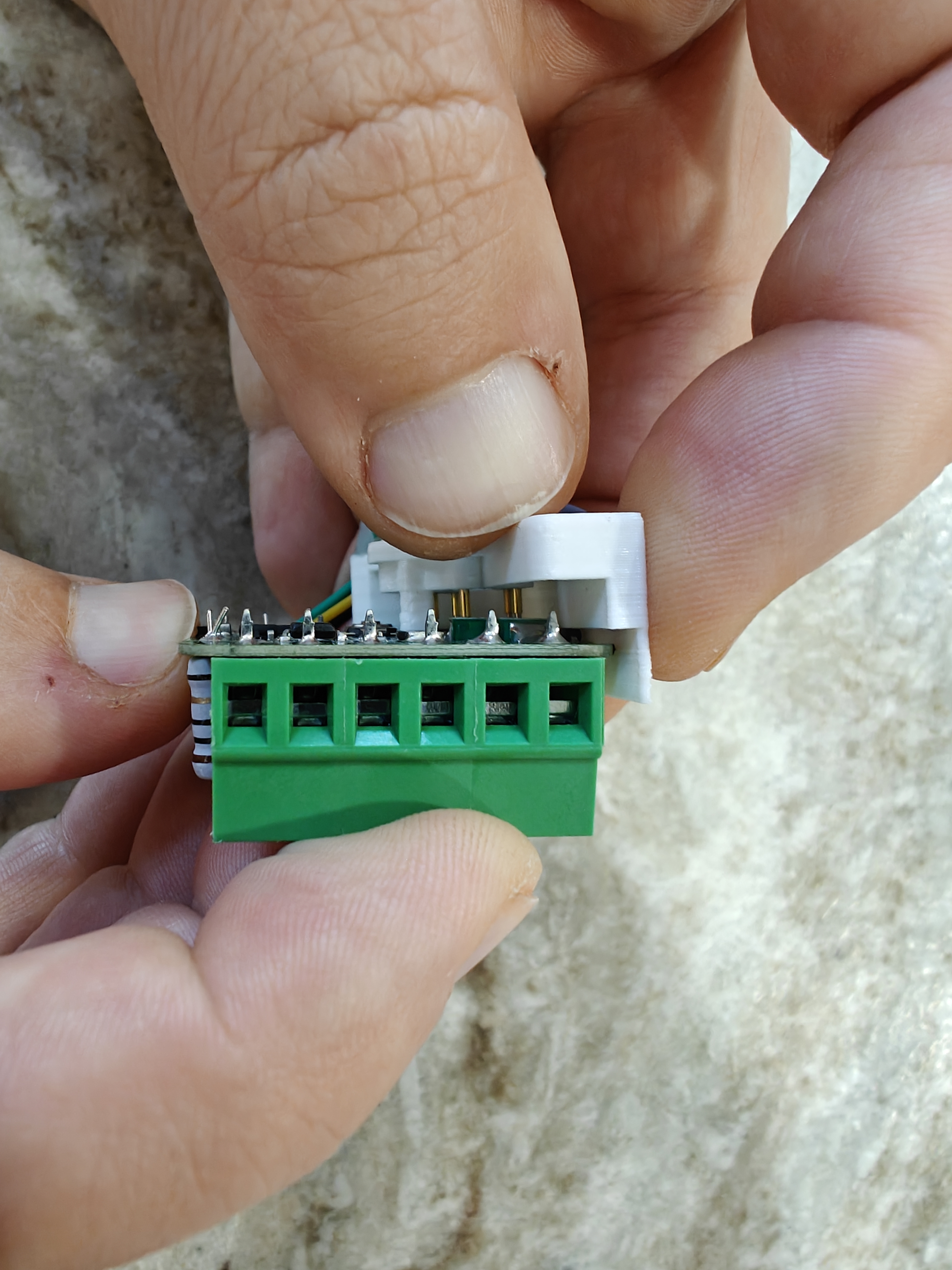
The jig is super simple to use. First you need to locate the board so the antenna goes into the angled slot of the jig. Push it into the wall of the jig. Then pivot the board so it makes contact with the pins.
 =>
=>
 =>
=>
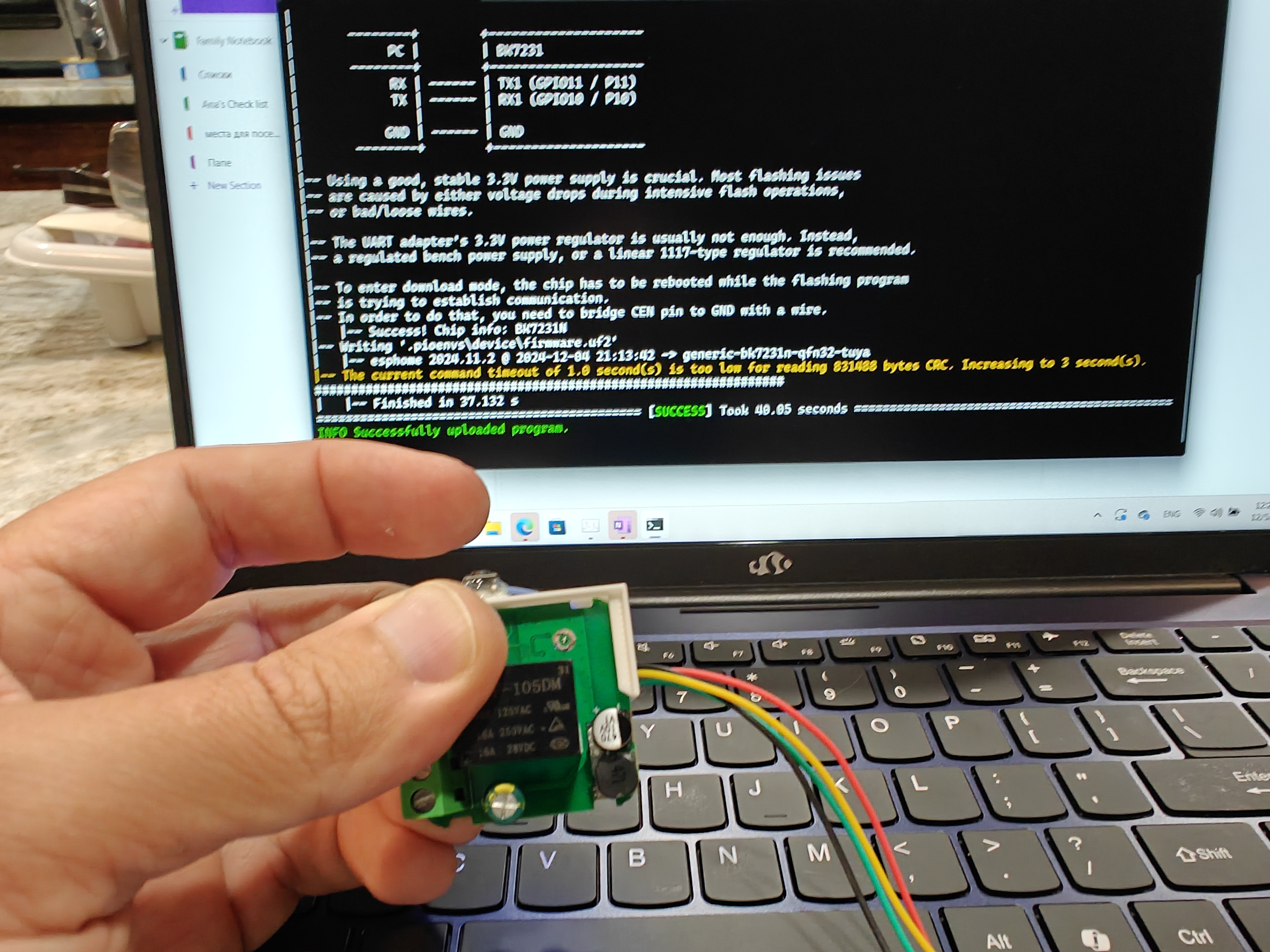
Finally, run the flasher command. Press and release the button when prompted to reboot the chip by bridgin the CEN pin to GND with the wire. Wait a couple of seconds. If nothing happens, press and release the button again. Try to not be super fast, but not too slow either. Ideally keep the button pressed for about quarter of a second.
That’s it. Well done!