
If you plan to flash more than just a couple ESP-02S modules or you’d like to avoid soldering the pads prior to installing the module, chances are you want to make this pogo pin jig.
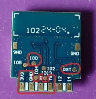
In order to flash the ESP-02S module, we need to connect 5 or 6 wires: Ground, +3.3V, RX, TX, IO0, and, optionally, Reset. Reset is needed if the chip boots up before the I00 pin is pulled low, thus releaseing UART port for application communications.
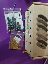
All ESP-02S modules share this layout, so to make it easy on yourself go ahead and make the jig! You will need:
- 3D-printed jig body (step and fusion files are avaiable as well)
- A few lengths of wire (I prefer flexible wires with silicone insulation)
- Tactile switch (see buying guide for sources)
- Pogo pins (see buying guide for sources)
The assembly process is very similar to that of Tuya Pogo Pin Jig, so I will not go as in-depth here.
Print the jig body and test it. The pogo pin must fit in the hole, but it has to be a really tight squeeze. If it wobbles inside, it might end up tilted and will not align with a pad on the board. If it’s too tight or too loose, please adjust the Hole Expansion setting in your slicer and try again.
I suggest using wires of different colors to make the assembly process more error-proof. I used 4 pieces of wire about 6 inches long each. Black for ground, red for power, green and yellow for RX/TX lines. I also used some other black cut-off for connecting the button. First step is to strip about 1/16” of insulation from both ends of all the wires and solder one on the end of each pogo pin. Please don’t hold pins with your fingers, use tweezers or pliers - things become hot very quickly. Better yet hold it with a clip. Use some flux and tin the end of each pin first. Once it is tinned, put a fluxed wire on top, add some solder to the iron tip and join the two together. After soldering is done, please check that pins are still springy and move freely. If not, desolder the wire, throw the pin away and try another one.
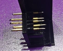
Press the pins into the jig body. It is very important to push them to the right depth. The moving part of the pin must protrude past the board stopping shelf. If it doesn’t protrude, then it will not make good contact. If it protrudes too far, then the board will not be able to get in position.
 (click to enlarge)
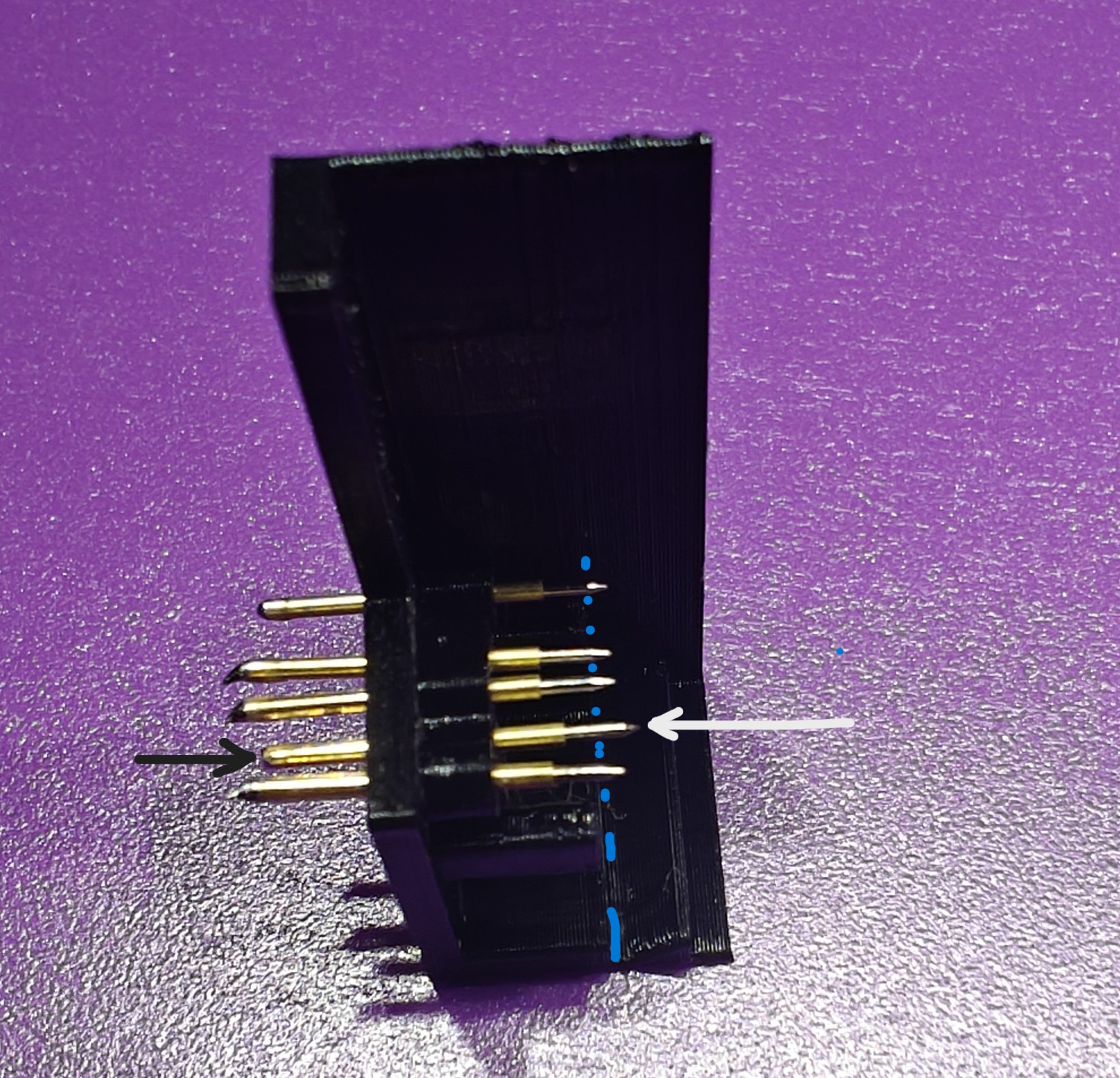
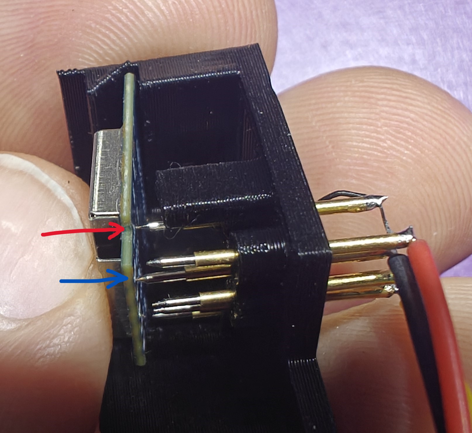
For the best possible performance I recommend to set all the pins to the same depth, except the GND pin (second pin in the staggered row of 4), which should be sunken slightly deeper (marked with arrows on the photo above). This ensures two pins: GND and IO0 make contact with the module first, so when the rest of the pins make contact and the chip powers up, it already has IO0 pulled low and enters bootloader mode automatically. This is completely optional, as you can always press the button to reset the chip. Once reset with all the pins connected, it also goes into bootloader mode.
 (click to enlarge)
As you can see, there are 2 pins touching first: IO0 is the one in the back (red arrow) and GND is the deeper set pin (blue arrow). The rest will make contact once the module is pushed all the way in. Again, this is completely optional, but is a nice quality of life feature.
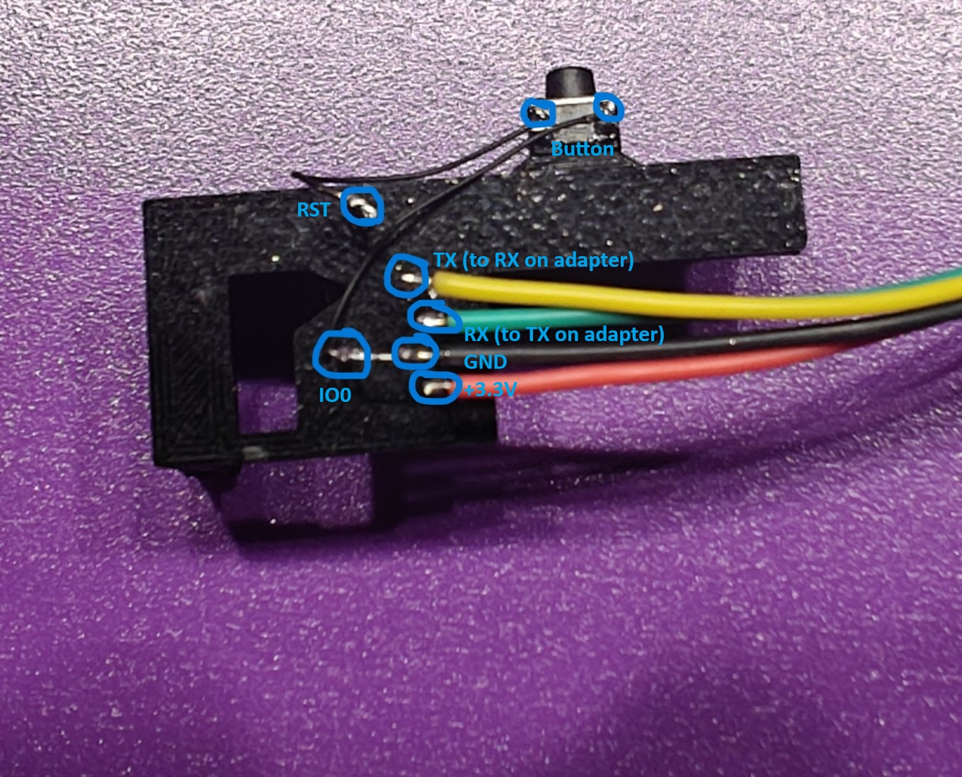
Pay attention to fit the pins in their proper places. Here’s how it should like after all the pins are pressed in. If you use different colors, just be sure to put 3.3, GND, RX, TX, IO0 and RST pins in their corresponding locations.
I tinned the pins prior to installation, but soldered the wires afterwards, hence you can see the wire between GND and IO0 is short. If you are not as proficient with the soldering iron, I recommend soldering the wires first. This means you need to solder a longer wire to these 2 pins. Button can be soldered after all the pins are put in place. Here is the complete connection picture:
 (click to enlarge)
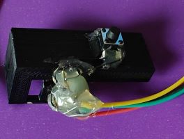
IO0 should be permanently connected to the GND and RST is connected to GND through the button. Button is super-glued to the pedestal on the side. I also like to apply some hot glue on top of everything. This is done to prevent the pins from sliding out (i know, we super-glued them in, but better safe than sorry) and to provide some stress relief to the wires. What could be worse than destroying your freshly made jig by accidentally tugging on a wire?
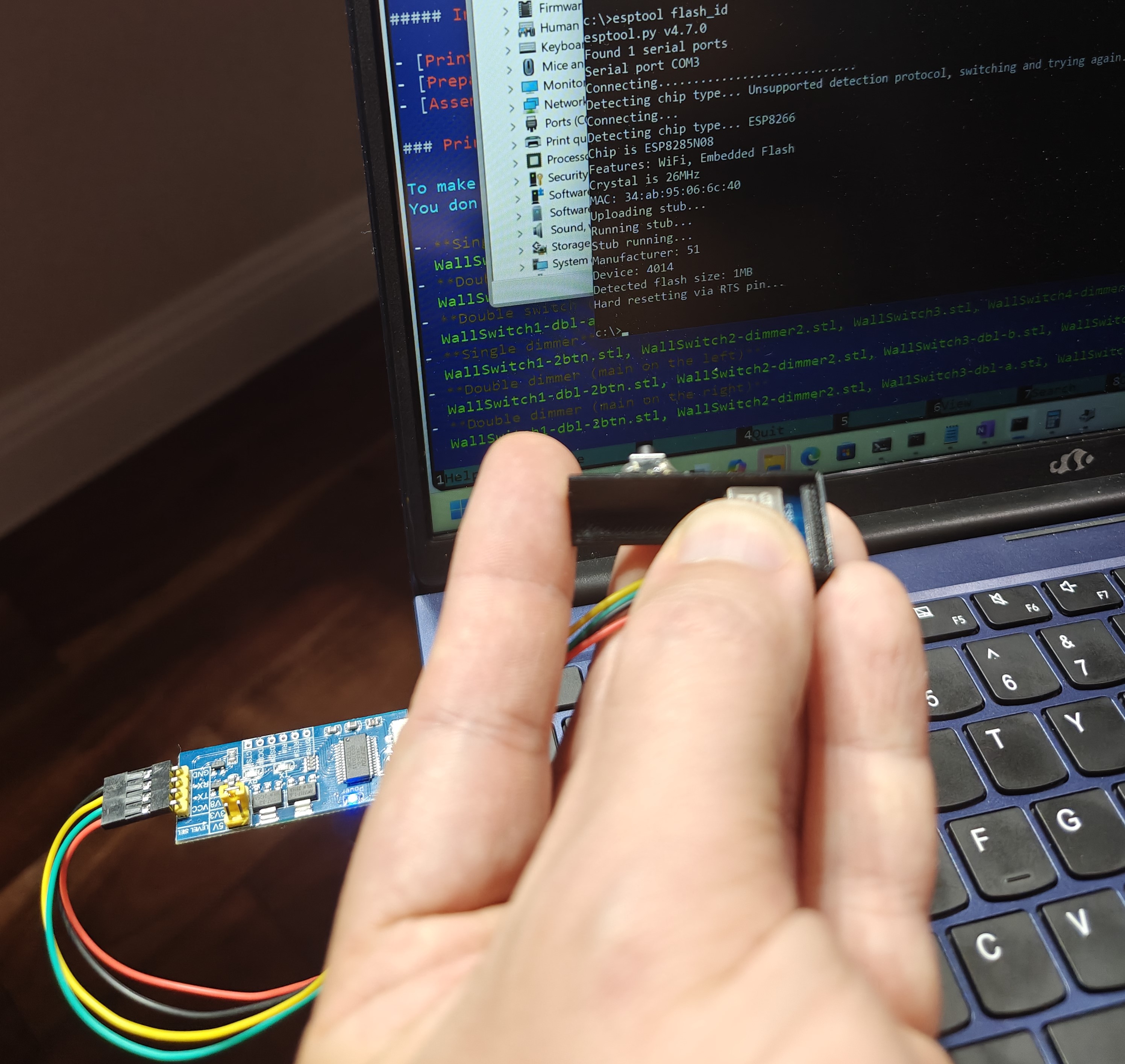
Final step is to try it out. Connect the jig to the USB-UART adapter, plug it in, place the module in, run the command.
I recommend testing with the esptool utility. I ran the esptool flash_id command. If it detects chip type and flash, everything works!
 (click to enlarge)
Congratulations! Now you have a jig to quickly flash ESP-02S modules.