
First thing we need to do with any device is to program it, so it does what we need to do.
I want to emphasize: it is really the first thing to do as we won’t have easy access to the contact pads in the later stages of the project. Feel free to jump to the relevant part of the guide:
- Setting up the environment
- Creating a firmware
- Single switch connections
- Double switch connections
- Dimmer connections
- Flashing the chip
- Flashing the dimmer MCU
Setting up the environment
In order to flash our own firmware we are going to need a few things first. We’ll be working with command prompt quite a bit, but don’t fret - it’s actually easy and only necessary for the very first firmware flashing. After that you have a choice to migrate your files into home assistant and manage all your devices’ firmware through the UI. I prefer to keep my files on the PC as it is much faster to generate and compile firmware. Here are the things needed to begin:
- Install git: Git - Downloading Package Leave everything default except a few things:
- When asked about preferred editor, choose something you already have installed and are familiar with. For beginners I recommend to choose Notepad
- Default branch name is up to you, I prefer to override it with main
- Install ESPHome. Official instructions here: Installing ESPHome Manually - ESPHome, but I found them to be incomplete.
So here’s my instructions, tested on a fresh PC:
- Install build tools from here: Microsoft C++ Build Tools - Visual Studio Select the “Desktop development with C++” tile and install.
- Install Python 3 from here: Download Python | Python.org Make sure to check both boxes at the bottom of the install screen (use admin and add to PATH). If prompted, disable the path 260 character limit.
- Start the command prompt as administrator (type “cmd” in your start menu search bar and select “Run as administrator”) and execute these commands:
pip3 install wheel
pip3 install esphome - Execute the command:
esphome version
If it prints the version, you succeeded.
- Increase UART buffer size. (this is optional)
ESPHome comes with built-in Arduino framework and uses it under the hood to build the firmware for our devices. Unfortunately (for us), Arduino framework is built to run on tiny microcontrollers, so buffers there are also quite small. Chips we will be using have a large amount of RAM available, so we can do better than just a few bytes. If you plan to make a device that relies on UART port (anything with power monitor, dimmers, etc.) then it’s advisable to increase the buffer size. This increases stability and reliability of communication between chips. To do it you need to edit the RingBuffer.h file from the arduino core library. You can do so by executing the following command from the administrator command prompt:
notepad %USERPROFILE%\.platformio\packages\framework-arduino-api\api\RingBuffer.h
or by editing this file with your text editor of choice. Either way, locate the following line:
#define SERIAL_BUFFER_SIZE 64
and change it to:
#define SERIAL_BUFFER_SIZE 1024
Save the file and close the notepad. - Get a local copy of all the necessary files. I like to create a “projects” folder on a C drive and store my projects there.
You can choose a different location, just make sure to substitute it when executing commands or working with files.
Open the command prompt and execute the following commands:
md c:\projects
pushd c:\projects
git clone https://github.com/ScramblerUSA/SimpleDiySmarthome.git(or you can fork the repository on github and clone your fork instead) - Copy the secrets template and fill in your passwords.
Go to the C:\projects\SimpleDiySmartHome\EspHome folder and find the secrets_template.yaml file.
Make a copy of this file and name it secrets.yaml You can also do it in the command prompt:
copy c:\projects\SimpleDiySmartHome\EspHome\secrets_template.yaml c:\projects\SimpleDiySmartHome\EspHome\secrets.yaml
Now open this file in the notepad (or editor of your choice) and fill in your WiFi network name and password:
notepad c:\projects\SimpleDiySmartHome\EspHome\secrets.yaml
This step is necessary to protect your secrets. secrets.yaml is a special file and it is excluded from git, so even if you commit your changes the secrets.yaml will be ignored and will only persist on your computer. - Install the driver for your USB-UART adapter if needed.
This step is specific to whatever adapter you are using. If the driver is required, you can usually download it from the manufacturer’s website.
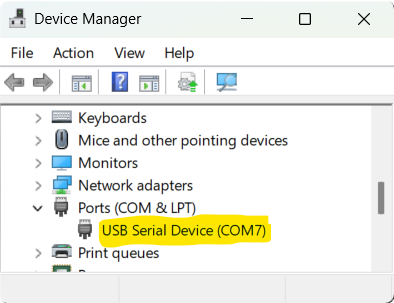
Most likely no additional driver is required. You can check it by opening the Device manager (type “device manager” in your start menu search bar).
You should see a new COM-port appear when you plug your adapter into a USB port:
Creating a firmware
You’ll need to create a firmware for your device before you can flash it. Don’t worry, it’s not hard at all. In fact with the templates I provided here you can do it in a few minutes. No coding required. There are 2 general approaches you can take:
- Create a firmware tailored for this specific device.
- Create a dummy firmware with OTA functionality enabled, so you can assemble the device now and flash the final firmware later via OTA.
I personally prefer to flash the dummy firmaware as it allows for faster batching. It also gives me an ability to produce a number of switches without defining their final name and location.
Dummy firmware
One caveat with dummy firmware is that at no time more than 1 dummy device should be connected to your network unless you change the name for each device. To create a dummy firmware follow these simple steps:
- Copy the files from the repository to your local folder. If you followed the Environment setup to the letter, these files should already be at your C:\projects\SimpleDiySmarthome\EspHome folder.
- Edit the Dummy.yaml file if you want to give it a unique name.
- Start a command prompt as an administrator and type the following commands:
pushd c:\projects\SimpleDiySmarthome\EspHome
esphome compile Dummy.yaml
It’ll take some time. Once you see theINFO Successfully compiled programmessage, your firmware is built.
Specific firmware
To create a device-specific firmware follow these simple steps:
- Copy the files from the repository to your local folder. If you followed the Environment setup to the letter, these files should already be at your C:\projects\SimpleDiySmarthome\EspHome folder.
- Make a copy the sample file for your device type (e.g. if you want a firmware for a single switch, use the SampleSingleSwitch.yaml file, etc.) and name it so it describes your device, e.g. DiningRoomSwitch.yaml
- Edit your newly created file with Notepad. Put your own names and descriptions. Comments (lines starting with #) will guide you.
- Start a command prompt as an administrator and type the following commands:
pushd c:\projects\SimpleDiySmarthome\EspHome
esphome compile DiningRoomSwitch.yaml(use your file name here)
It’ll take some time. Once you see theINFO Successfully compiled programmessage, your firmware is built.
Single switch connections
Single switches come in a variety of types.
Here are some most common board layouts covered by this guide: simple switch, switch with RF receiver, switch with power meter.
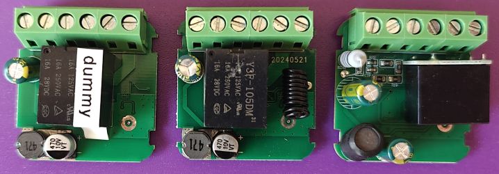
(never mind the “dummy” sticker, that’s my shenanigans, I like to label my devices to not mix them up)
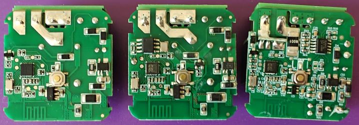
All these boards share a common layout part: a BK7231N chip with 6 contact pads surrounding it.
This opens up a possibility to use a jig for quick flashing of small batches of switches, which is great as single switches are probably the most common type of a switch around the house, so chances are you’ll need more than one.
If you’ll be making only a few switches or just don’t want to make a jig, here’s how to connect the switch for flashing.
As always in DIY, there are many ways to do it.
 (click to enlarge)
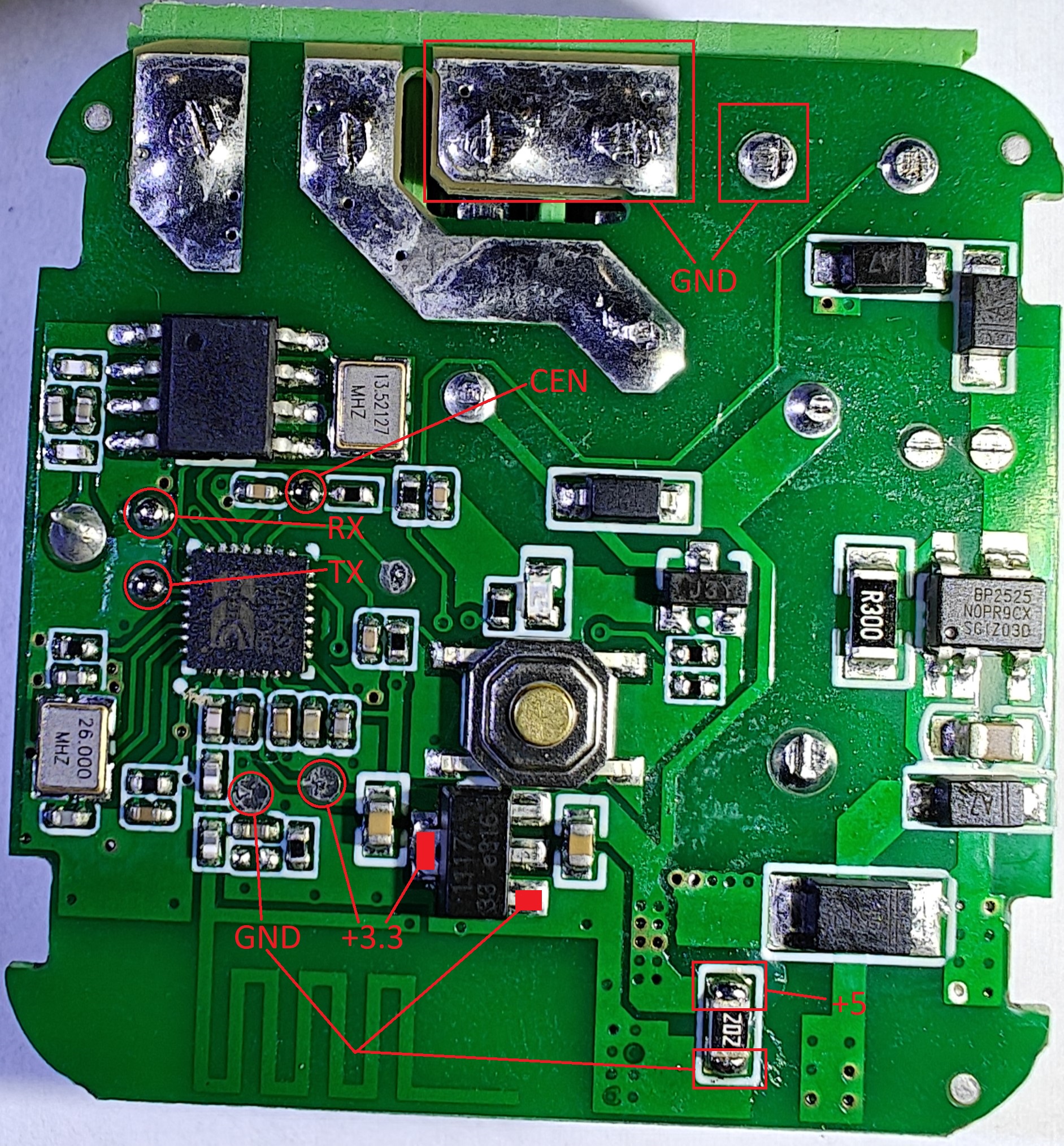
Here are the pads we need to solder wires to.
Attention! RX and TX labels on pads describe where to connect them on your USB-UART adapter, not the actual RX/TX designation of the chip which are reversed. So if you see TX here - this is where to connect TX pin of UART, and RX denotes where to connect RX pin of UART.
For RX and TX there are only a single spot to do so. With power and ground, however, there is a bit of freedom.
For GND connection choose whatever the easies for you is.
For power connection there are 2 options on these boards: 3.3 volts and 5 volts.
- If you have a USB-UART adapter with powerful enough voltage regulator (AMS1117) that can power up the board directly, then connect to +3.3 pad to the adapter’s 3.3v output.
- If you have a USB-UART adapter with weak voltage regulator or you are not sure, then connect +5 pad to the adapter’s 5v output.
CEN is a little special, it doesn’t connect to the USB-UART adapter. Instead, solder a short piece of wire to it - you will need to briefly touch the GND pad with this wire at the beginning of the flashing process. This is optional.
With all wires soldered it should look something like this: 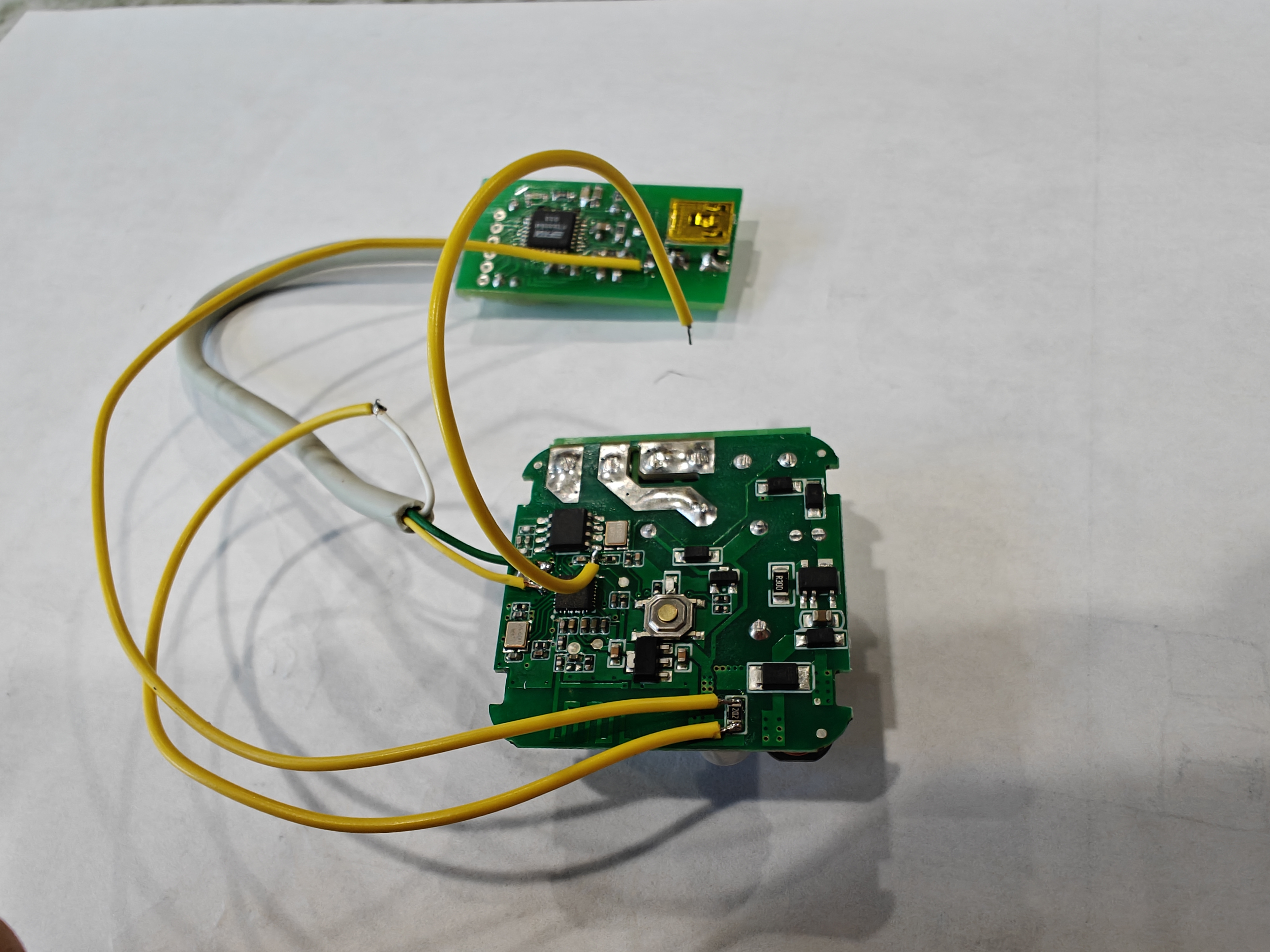
Now that we are done with connections, it is time to flash the chip.
Double switch connections
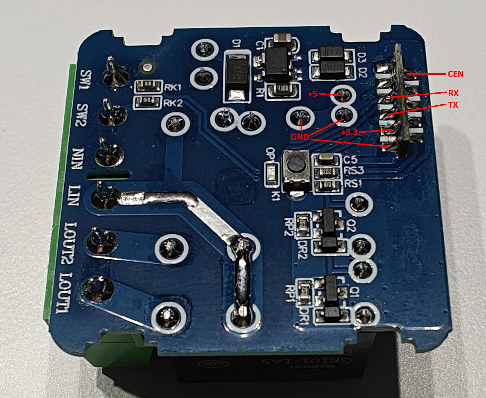
So far I encountered only one board layout for double (2-gang) switch. Here it is:
 (click to enlarge)
Unfortunately, there are no test pads, so we can’t use a jig here and the only way to flash it is to solder wires to the board (the jig for 2-gang switches is in the works and will be published soon).
Luckily it is not hard at all. All the contacts are easily accessible.
Attention! RX and TX labels on pads describe where to connect them on your USB-UART adapter, not the actual RX/TX designation of the chip which are reversed.
So if you see TX here - this is where to connect TX pin of UART, and RX denotes where to connect RX pin of UART.
For RX and TX there are only a single spot to do so. With power and ground, however, there is a bit of freedom. For GND connection choose whatever the easies for you is. For power connection there are 2 options on these boards: 3.3 volts and 5 volts.
- If you have a USB-UART adapter with powerful enough voltage regulator (AMS1117) that can power up the board directly, then connect to +3.3 pad to the adapter’s 3.3v output.
- If you have a USB-UART adapter with weak voltage regulator or you are not sure, then connect +5 pad to the adapter’s 5v output.
CEN is a little special, it doesn’t connect to the USB-UART adapter. Instead, solder a short piece of wire to it - you will need to briefly touch the GND pad with this wire at the beginning of the flashing process. This is optional.
Now that we are done with connections, it is time to flash the chip.
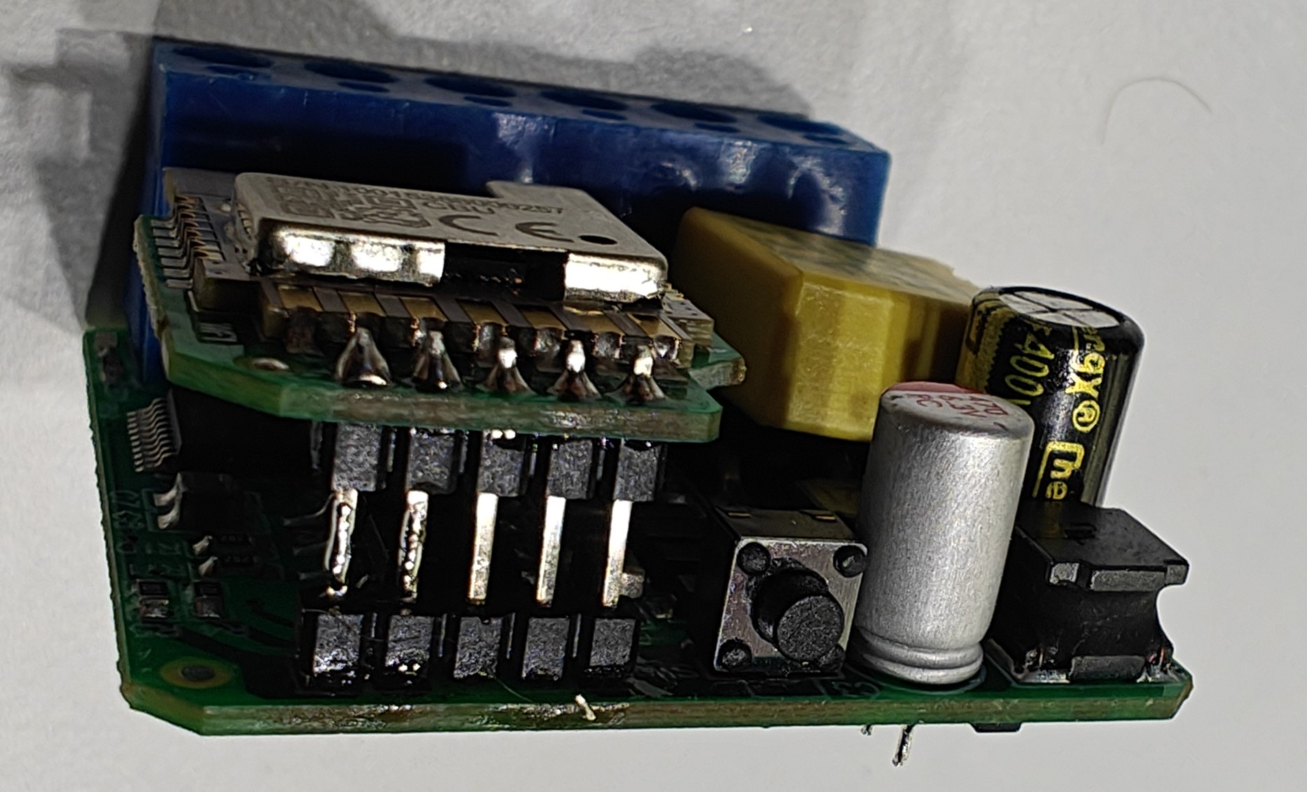
Dimmer connections
The only model of dimmer covered by this guide is the Avatto dimmer, which comes in 2 variations: 1-gang dimmer and 2-gang dimmer.
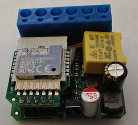
Both of them share the same board (or rather a 2-board sandwich) which looks like this:
These by far are the most difficult to work with. I’ll cover a few ways to connect to both the WiFi chip and MCU chip.
If you have the proper equipment (see the tools buying guide for T12 station and tips), then you can desolder the WiFi module and the rest is trivial. You can also use solder-sucking desoldering gun if you have one.
Once desoldered, you can easily connect to the pins of the module: 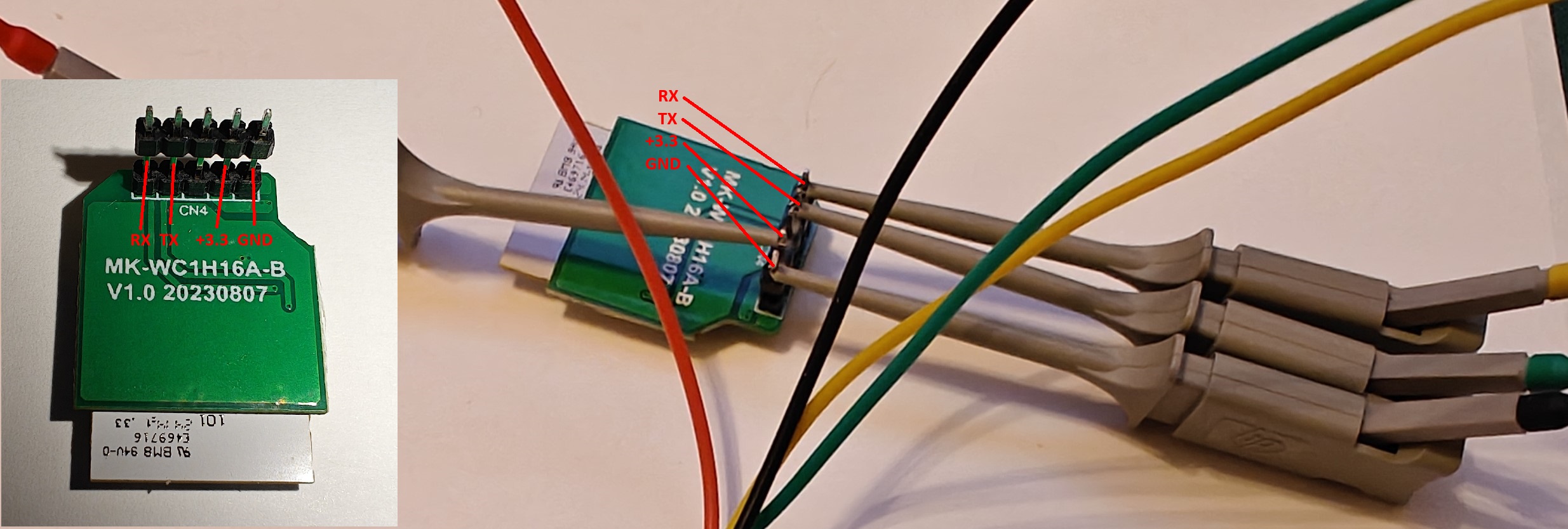 I recommend using IC clips (see tools buying guide) to quickly connect and avoid soldering altogether.
Attention! RX and TX labels on pads describe where to connect them on your USB-UART adapter, not the actual RX/TX designation of the chip which are reversed. So if you see TX here - this is where to connect TX pin of UART, and RX denotes where to connect RX pin of UART.
I recommend using IC clips (see tools buying guide) to quickly connect and avoid soldering altogether.
Attention! RX and TX labels on pads describe where to connect them on your USB-UART adapter, not the actual RX/TX designation of the chip which are reversed. So if you see TX here - this is where to connect TX pin of UART, and RX denotes where to connect RX pin of UART.
If you are unable to desolder the module, do not fret! There is another way.
We need to cut one of the pins to disconnect MCU line so it doesn’t interfere with the flashing process.
Using your side cutters, snip the second pin in the middle: 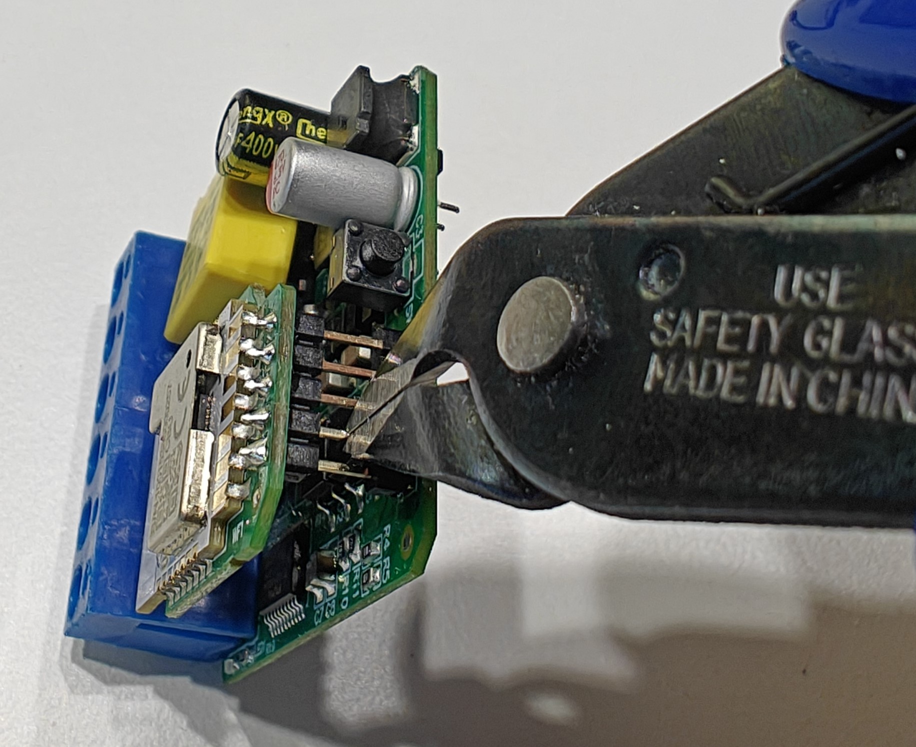
Then snip it again to cut a tiny piece off: 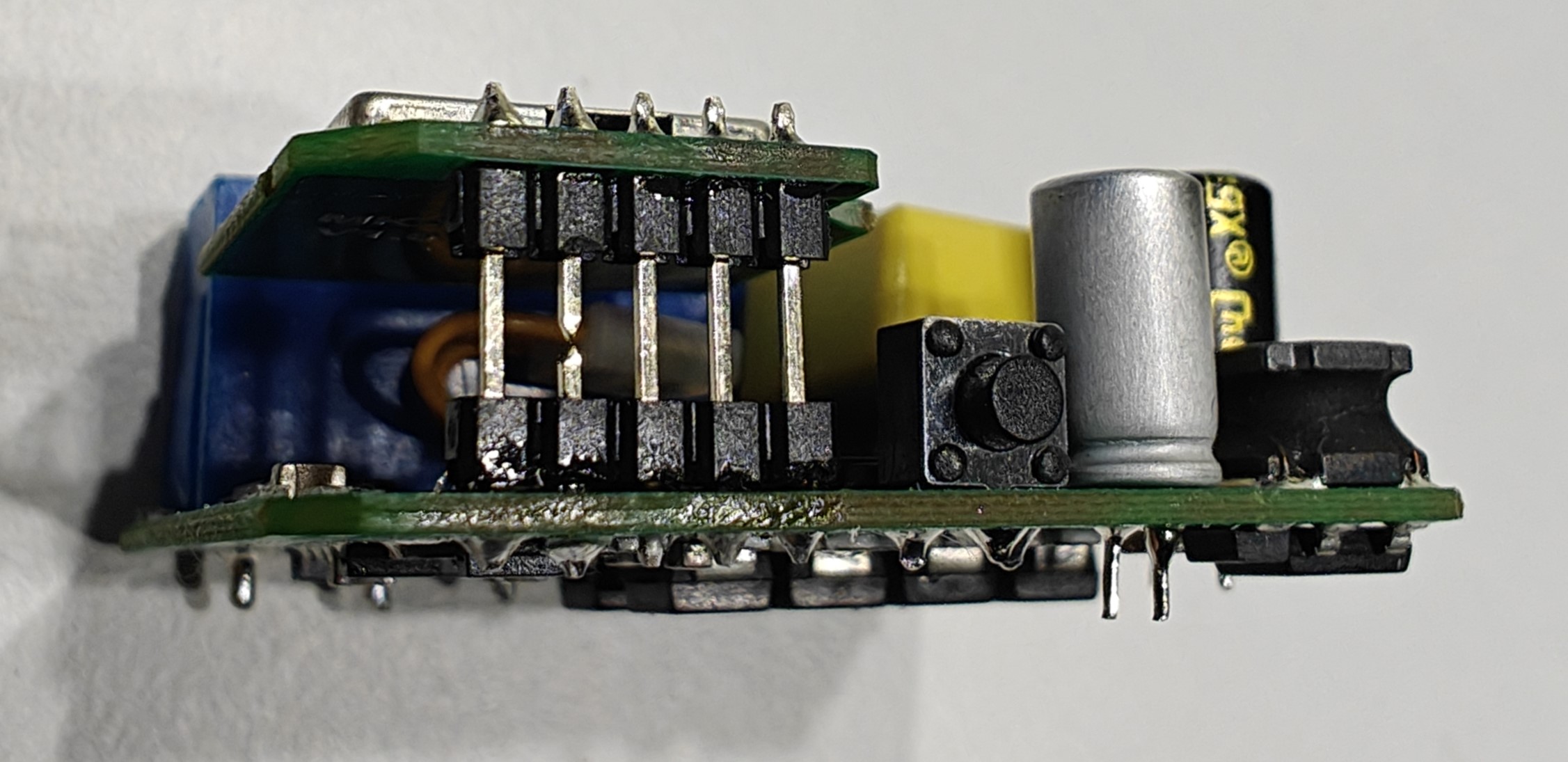 so the pin parts do not touch each other.
This is how NOT to do it: 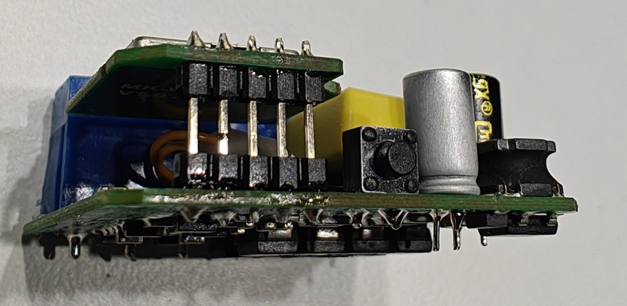 - as you can see despite being cut, parts of the pin still touch each other.
This is enough for MCU to send a signal and disrupt the flashing process.
- as you can see despite being cut, parts of the pin still touch each other.
This is enough for MCU to send a signal and disrupt the flashing process.
After you cut the pin, connect the clips: 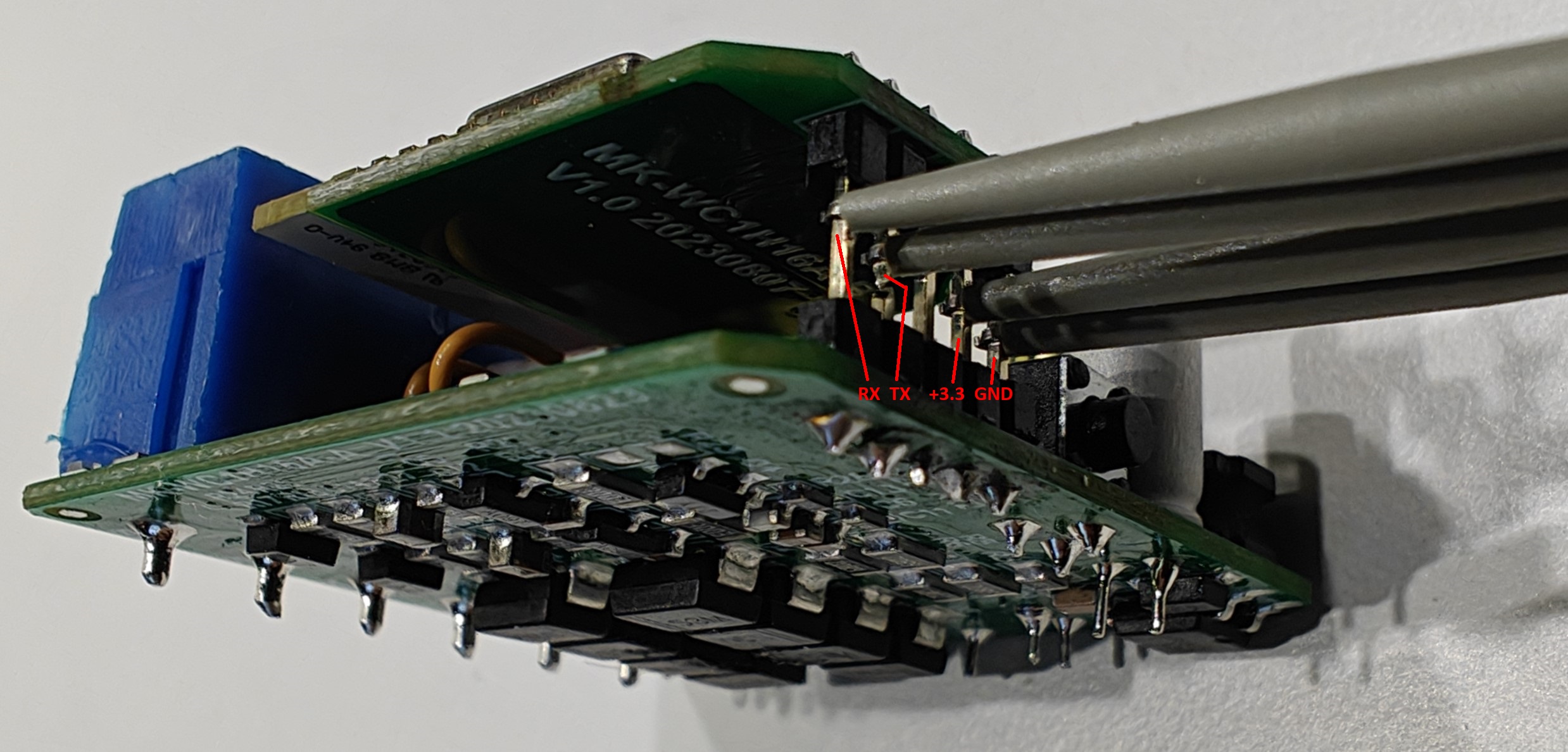 or solder the wires.
Now that we are done with connections, it is time to flash the chip.
MCU connections
If you want to add a ceiling fan control to the dimmer or just want to replace the stock firmware, here’s how to connect.
If you desoldered the module, connection is pretty trivial: 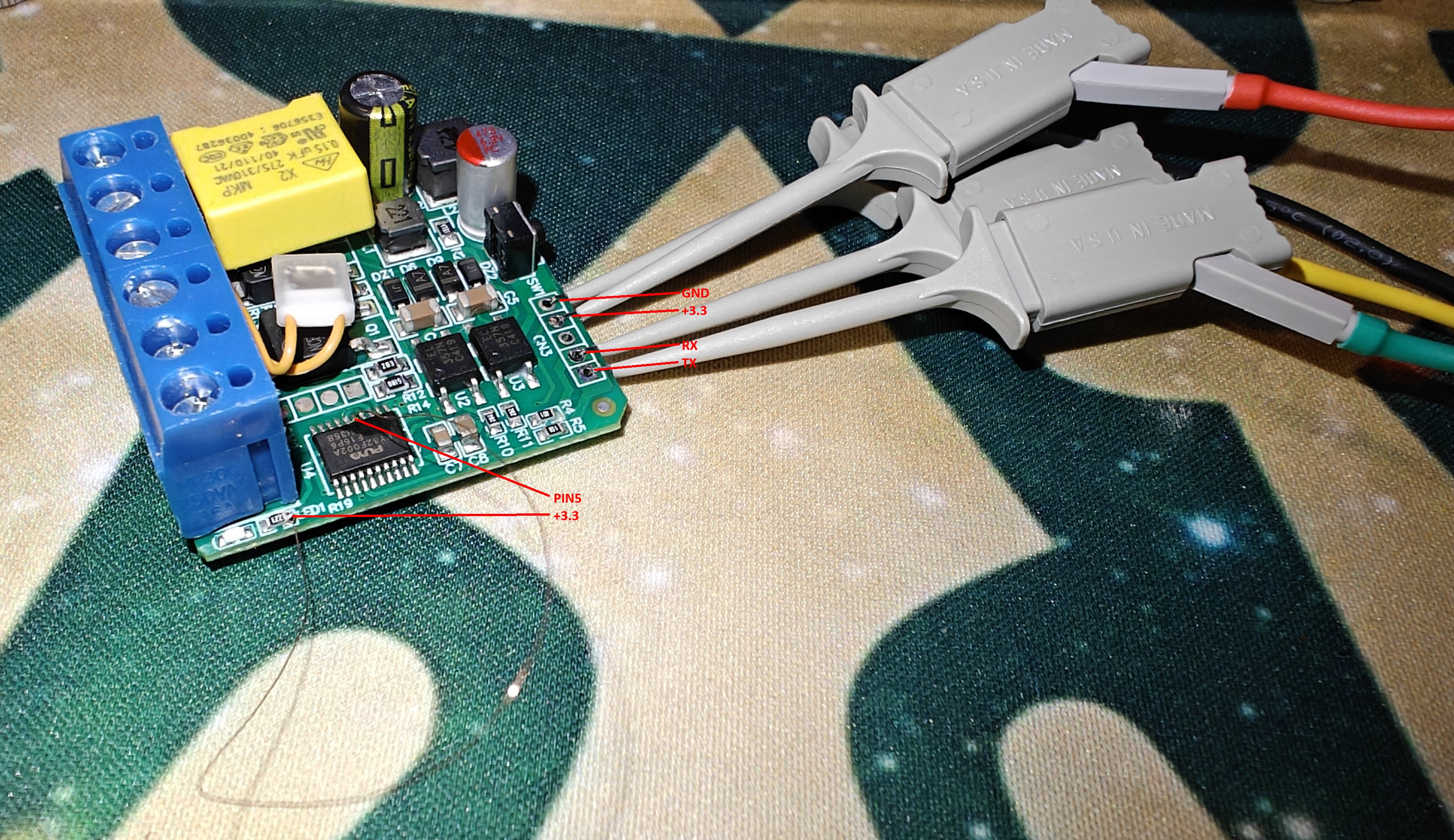
On this picture you can see the UART connection as well as a wire soldered to PIN5 connecting it to +3.3V. This is some very fine soldering.
Alternatively you can use the resistor method described below.
Attention! RX and TX labels on pads describe where to connect them on your USB-UART adapter, not the actual RX/TX designation of the chip which are reversed. So if you see TX here - this is where to connect TX pin of UART, and RX denotes where to connect RX pin of UART.
If you can’t desolder the module, there is an alternative solution again!
Only this time we need to cut 2 pins: 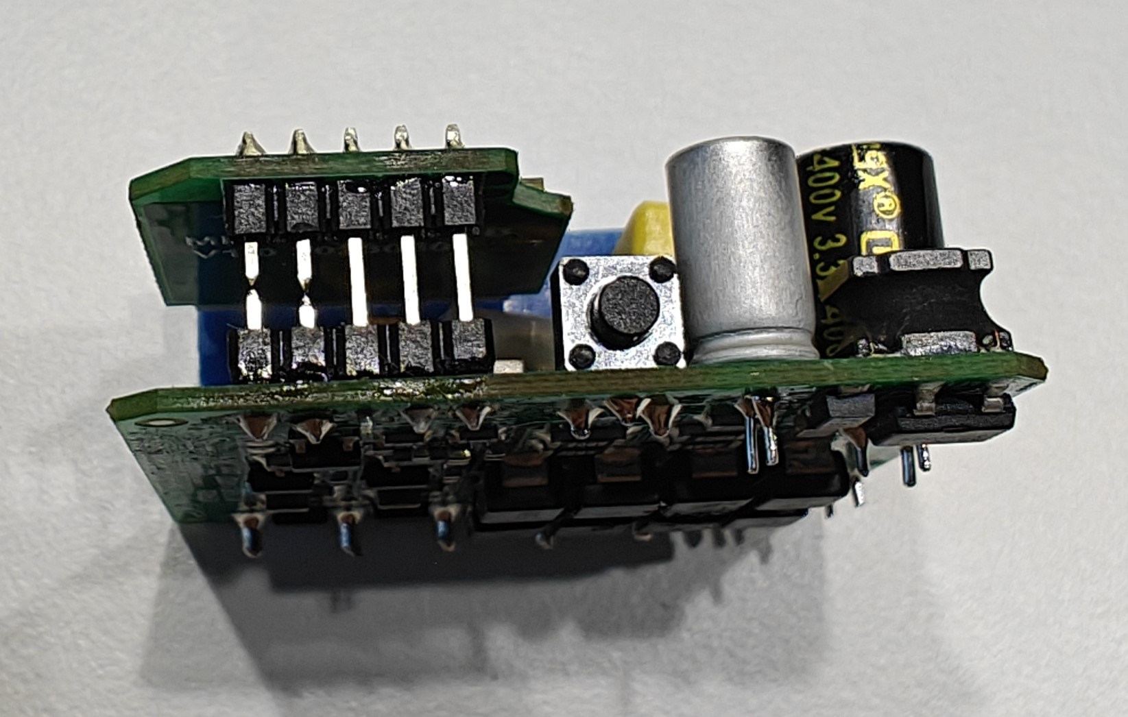
After that we can connect using IC clips or by soldering the wires: 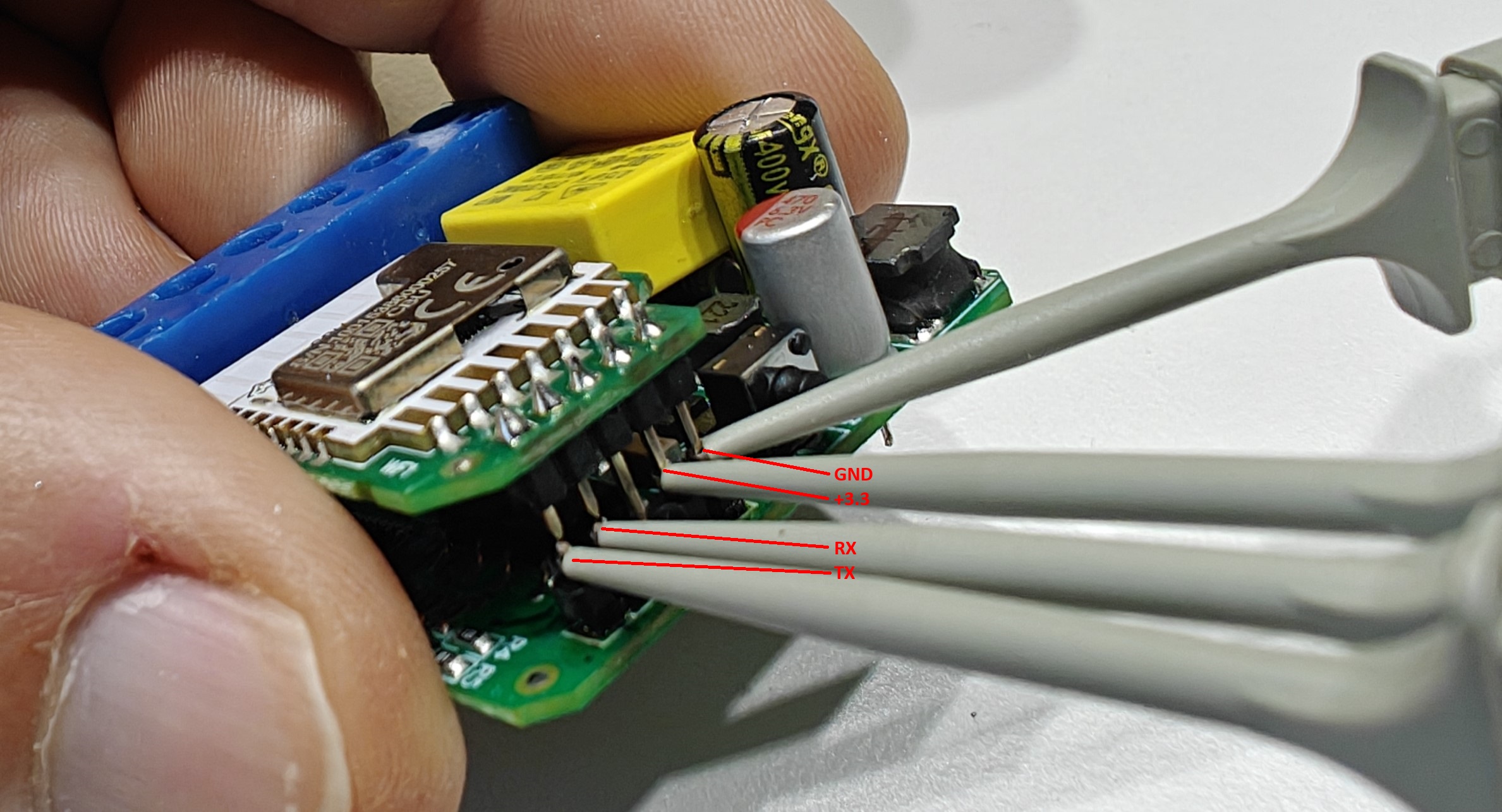
However, we still need to provide the +3.3V signal to the PIN5 of the MCU to put it into the boot mode: 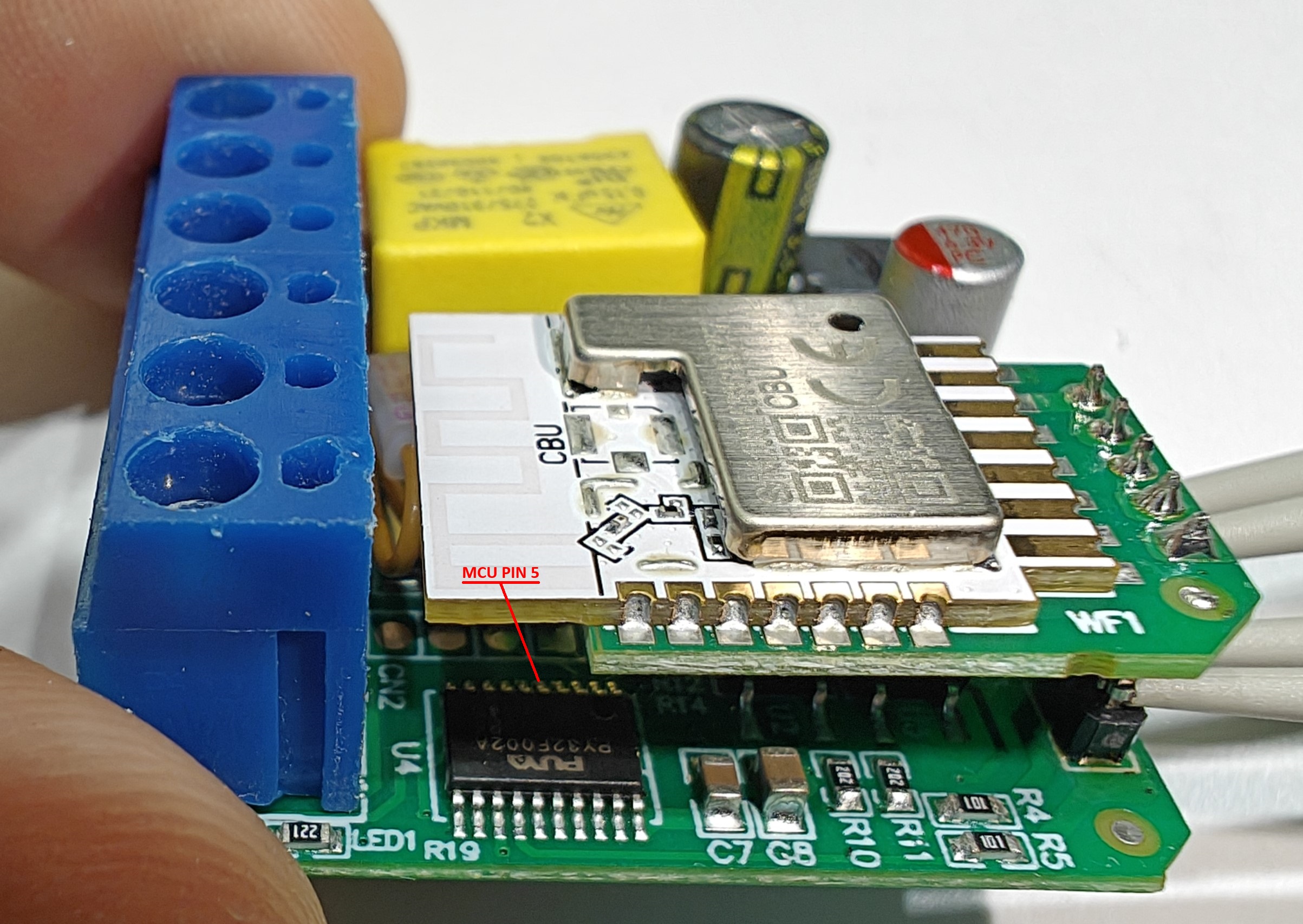
This pin is not easily accessible as the module covers the MCU chip. So you can use the resistor method.
The resistor method.
PIN5 is the pin responsible for putting the MCU into boot mode, so we can reflash it.
Lucky for us both neighboring pins are not used and are configured as inputs by default, so we can connect them without fear of burning the chip.
To do this we will need a resistor. Anything between 1K and 10K should work just fine. I used 10K in my experiments.
Solder a wire to one side of the resistor.
Then connect another end of the wire to +3.3 volt source - either splice it to the wire where the +3.3 clip is connected, or solder it to any available +3.3 pad on the board.
Connecting it to the clip is preferred because it allows you to program multiple boards without re-soldering this wire.
Easily accessible locations are the +3.3 pin of the module and the right side of the LED resistor. Bend the other resistor lead in L-shape.
Now you can touch the PIN5 with it without worry - you won’t fry anything: 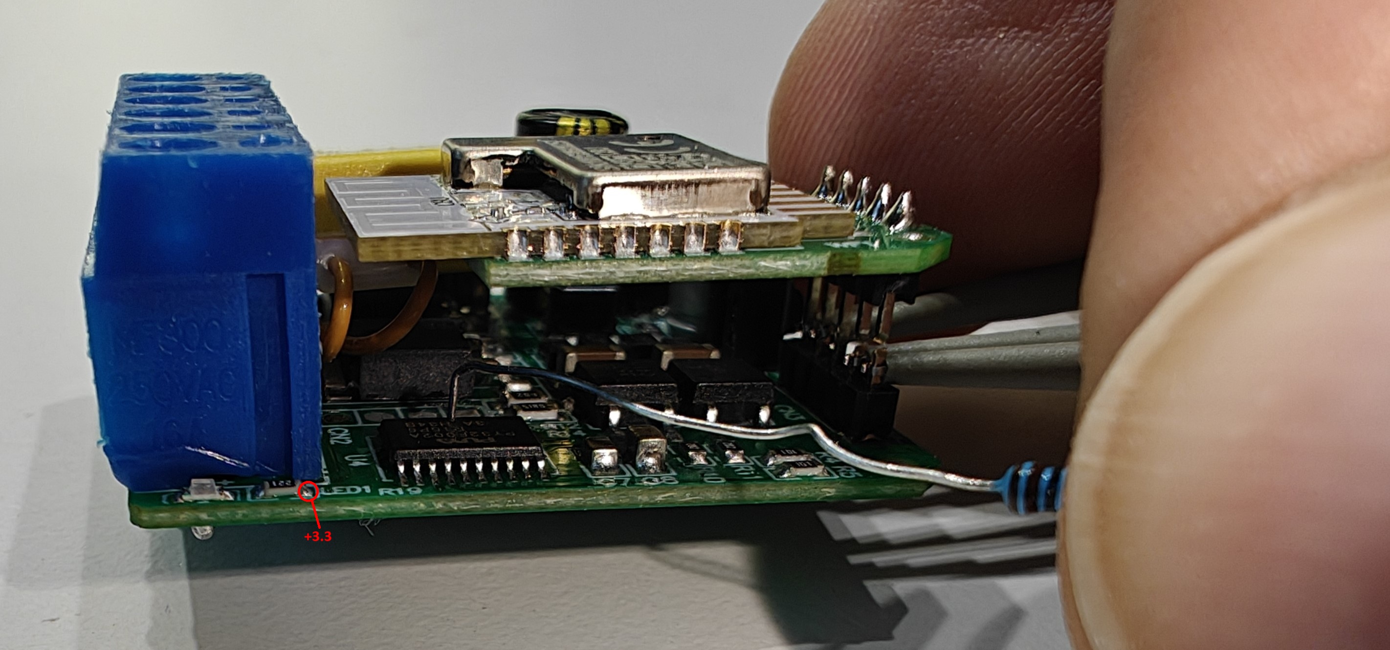
It’s OK to touch PIN4 or PIN6 as well, no harm will be done.
After flashing is done, you can easily repair the cut pins with some solder and flux:
Flashing the chip

Pro tip: mark the board after flashing. I like to put a label, showing what firmware is flashed. You can use a random small sticker as well. A permanent marker works too. Anything to help you keep track if the board was flashed or not.
Flashing the dimmer MCU