Finally, we are at the assembly stage. At this point you should have all the parts ready and the board flashed with your firmware.
Please refer to the prior steps if you have something missing:
In this guide
Printing the parts
To make a device you will need a specific set of parts to be printed. You can find all the models in STL format here: https://github.com/ScramblerUSA/SimpleDiySmarthome/blob/main/3DModels/ You don’t need to print everything though! Here are the lists for each device:
- Single switch
WallSwitch1.stl, WallSwitch2.stl, WallSwitch3.stl, WallSwitch4.stl, WallSwitch5.stl - Double switch (main on the left)
WallSwitch1-dbl-b.stl, WallSwitch2-2ch.stl, WallSwitch3-2ch-a.stl, WallSwitch3-dummy-a.stl, WallSwitch4-2ch.stl, WallSwitch5-2ch.stl, WallSwitch6-dbl.stl - Double switch (main on the right)
WallSwitch1-dbl-a.stl, WallSwitch2-2ch.stl, WallSwitch3-2ch-b.stl, WallSwitch3-dummy-b.stl, WallSwitch4-2ch.stl, WallSwitch5-2ch.stl, WallSwitch6-dbl.stl - Single dimmer
WallSwitch1-2btn.stl, WallSwitch2-dimmer2.stl, WallSwitch3.stl, WallSwitch4-dimmer2.stl - Double dimmer (main on the left)
WallSwitch1-dbl-2btn.stl, WallSwitch2-dimmer2.stl, WallSwitch3-dbl-b.stl, WallSwitch3-dummy-b.stl, WallSwitch4-dimmer2.stl, WallSwitch6-dbl.stl - Double dimmer (main on the right)
WallSwitch1-dbl-2btn.stl, WallSwitch2-dimmer2.stl, WallSwitch3-dbl-a.stl, WallSwitch3-dummy-a.stl, WallSwitch4-dimmer2.stl, WallSwitch6-dbl.stl

Dimmer with ceiling fan speed controller (main on the left): WallSwitch1-dbl-2btn.stl, WallSwitch2-dimmer2.stl, WallSwitch3-dbl-b.stl, WallSwitch4-dimmer2.stl, TBDDimmer with ceiling fan speed controller (main on the right): WallSwitch1-dbl-2btn.stl, WallSwitch2-dimmer2.stl, WallSwitch3-dbl-a.stl, WallSwitch4-dimmer2.stl, TBD
Preparing the parts
Some smaller parts (WallSwitch4, WallSwitch5, and their variants) have built-in adhesion pads and supports - those need to be removed. I designed them this way to simplify batch printing in ABS, which is prone to warping. While printing a full bed of parts I ran into the issue of just one part peeling off, knocking off half the parts like dominos. I tried printing with a brim, but it is absolutely not needed for larger parts and cleanup is painful since the brim surrounds parts completely.
Switch rocker needs to be prepared as described on the Teardown page.
Assembling the device
Make sure you flashed the board before assembly! Putting it in the case will make contact pads inaccessible, making wired flashing impossible. Since assembly process relies on gluing parts together, the only way to access the board again is to carefully destroy the case without damaging the board.
General idea is the same across all types of switches. The board goes into the case (part #2) and is fixed in place with spacers (parts #4, #5). At this point all the final solder connections can be made. The case is then glued to the frame (part #1). Now the button is connected (3 buttons for 2-gang models). Finally, the remaining open frame is covered with a cover (part #3). For 2-gang models there is also a large cover for the second switch frame (part #3-dummy) and a wire channel cover (part #6).
Assembling a single switch
Single switch assembly begins with soldering a couple of wires to the board. Make sure your board is flashed!
Wires need to be soldered to the spots shown on this picture:
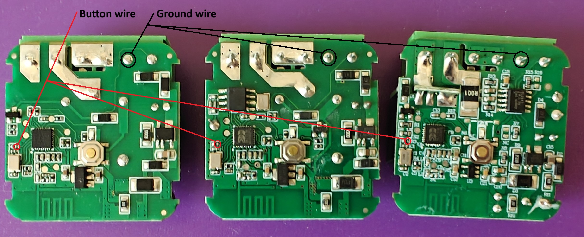 (click to enlarge)
3 boards are shown here: regular switch, switch with RF module, switch with power monitor.
(click to enlarge)
3 boards are shown here: regular switch, switch with RF module, switch with power monitor.
Ground wire is very easy to solder. It is helpful to orient it horizontally when soldering. Button wire is a little bit tricky, but you can do it! All you need to do is to strip a very short piece of insulation from the wire (about 1mm or 1/16”) and pre-tin it. Now apply some flux to the contact point, bring the wire and heat everything with a fine tipped soldering iron. It will melt solder on both the wire and the contact point, allowing them to fuse together. Remove the iron and you are done.
Next step is to glue a tactile switch in its place in the switch frame (WallSwitch1.stl). Photo is missing! :(
Now place the board into the housing and put 2 retainers in: photo is missing! :( Apply super glue around the rim of the housing and glue it to the frame: photo is missing! :( Solder 2 wires to a tactile switch: photo is missing! :( Glue the small cover to the frame: photo is missing! :( Now all that remains is to insert the bumper into the hole above the button and insert the rocker into frame. Make sure to orient it so the window is above the switch board.
Fine tune the rocker. If you are not satisfied with the feel of your newly assembled switch (rocker has a lot of play without pushing the button) it’s easy to fix. Use a large flat screwdriver to carefully pry the rocker off. Glue on a shim. Assemble it back.
Assembling a 2-gang switch
Assembling a dimmer
Assembling a dimmer with fan control